Table of Contents
Wheel Controller 3D Manual
Setup
For WC3D to work properly, the vehicle model should have Unity-correct rotation and [1,1,1] scale. More about that here.
Vehicle Model
- Drag the model into the scene. The model should have correct rotation and 4 separated wheel meshes. This example will use the included Niva model.
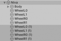
- Example vehicle hierarchy:
- Add a Rigidbody to the vehicle and adjust the Mass to 1400.
- Attach a Collider to the vehicle. Collider is required for Rigidbody to work properly.
Wheels
- Create empty GameObjects to hold the WheelController script. Position of this object will act as the suspension origin. These objects can be created by duplicating the wheel objects and stripping them of all the components, except for the Transform:
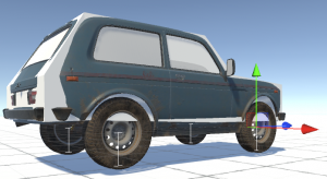
- Attach WheelController script to the newly created empty objects. If Gizmos are enabled, the vehicle should now show the suspension travel gizmos (white):
- WheelController > Parent field should be automatically set to the earlier added Rigidbody (Niva in this case).
- Select each WheelController component and assign the corresponding Visual (mesh).
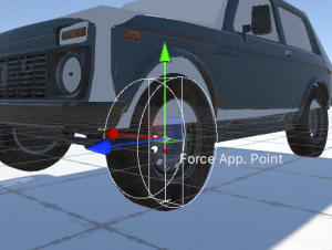
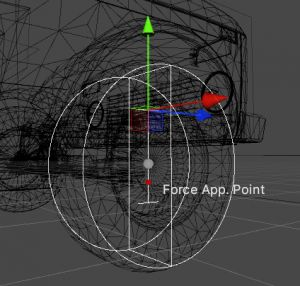
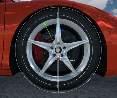
- The wheel gizmo now shows up. If the width or radius do not match the actual wheel width or radius, adjust the values manually.
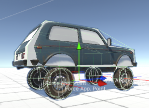
- After pressing play the vehicle should look something like the screenshot below:
- Note the high ride height. To adjust this, grab the GameObjects containing the WheelController scripts and drag them up. The travel indicator (capital I) will move with the objects and indicates the top and bottom of the suspension travel:
Car Controller
If using the WheelController3D standalone asset, use the provided CarController script. Otherwise, if using it as a part of the NWH Vehicle Physics 2 asset skip to the VehicleController quick start guide.
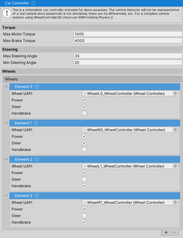
- Attach the CarController script to the vehicle.
- The wheels will be found automatically, but the Steer, Handbrake and Powered fields might need adjusting depending on the wheel order.
- Given that all the steps have been correctly followed, the vehicle will drive around normally at this point.
Variable Center of Mass
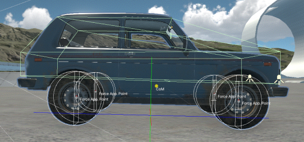
If the collider added previously is small (in relation to the size of the vehicle) or offset, Variable Center of Mass script can be used to adjust the center of mass and inertia values of the vehicle.
- Center of mass gizmo should appear around the centre of the vehicle.
- Inertia for a typical car should be around [700, 1400, 400] or larger. Too low inertia causes jitter/floating of the vehicle, too high makes the vehicle feel like it is very heavy and resist rotation. Usually it is better to aim for larger value if this is suspect.
Adjusting the Behaviour
If you have no knowledge of how suspension works I would recommend checking out this link first. Also, check out FrictionPreset page.
Tips
WheelControllerTransformrepresents the origin of the suspension. Its position directly affects the position of the suspension and the wheel. So, to raise the vehicle, lower theTransform, and vice versa. To achieve wider track (distance between wheels on the same axle), move theTransformoutwards. And finally, to achieve toe and caster angles, rotate theWheelControllerTransform. Example caster adjustment:
- Using very short spring rates might result in suspension bottoming out when wheel travel in one frame is larger than the total length of the spring. About 0.2m is the recommended minimum spring length value for default Time > Fixed Delta Time setting.
- Vehicles without suspension are supported. In that case a native MeshCollider will be used for collision, while the friction will still be calculated by the WheelController. To use a WheelController without a suspension, set the spring length to 0.
Reducing Roll
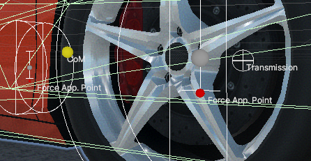
- The lower the center of mass is, the less roll the vehicle will have in corners. If too low, the vehicle will start rolling in the opposite direction than expected. The center of mass can be adjusted through the
VariableCenterOfMassscript, or through theRigidbodyinspector in the newer versions of Unity. - Increase the Wheel Controller > Force Application Point Distance to a higher value. This is the point at which the friction forces will be applied, and value of 1 means one spring Max Length above the ground.
Achieving Oversteer
- Reduce the Friction > Lateral Friction > Grip on the rear wheels.
- Adjust Center of Mass forwards through the Variable Center of Mass script.
- Increase the spring rates on the rear wheels. Stiffer rear suspension, compared to front, generally results in more oversteer.
- Reduce the roll of the vehicle through the center of mass or the
Force Application Point Distance. Lower center of mass and higher force application point distance equals less roll, which in turn equals more oversteer.
Arcade-like Behavior
By default the asset is geared towards realism. To achieve arcade-like behavior:
- Reduce
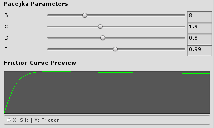
Slip Coefficientand increaseForce Coefficient. This will cause the vehicle to be less prone to slipping and spinning out. Good starting values are 0.5 for slip coefficient and 2 for force coefficient. - Adjust the friction curve to be more linear. You might need to increase the
Force Coefficientto make vehicle slide less afterwards (for the curve in the image below force coefficient of 12 was used):
- Lower the center of mass to reduce the chance of vehicle flipping over and make vehicle lean less making it behave more like a go kart. Do not lower center of mass below the axle height or the vehicle might begin to lean in the opposite direction.
Considerations
While WheelController is quite flexible, there are a few things to keep in mind when designing a game around it. Most of these points apply to any wheel collider/controller that uses the inverse kinematics approach to wheel positioning, which positions the wheel on the ground and then calculates suspension forces. This approach results in excellent performance, stability, and reliability. Keep the following considerations in mind:
- Ground detection occurs over the entire bottom half of the wheel, but not the top. Collisions on the top half of the wheel are handled by a native MeshCollider. This means that wheels do not work when the contact surface is on top of the wheel. Tips:
- It's a good idea for the vehicle body collider to cover the tops and sides of the wheels. However, in cases like a monster truck, it is perfectly fine for the wheels to stick out.
- Ideally, driving on the vehicle side should be avoided as a game mechanic.
- Due to potentially large suspension forces, it's advisable to set the
Other Body Force Scaleto <1. This reduces the forces applied to other Rigidbodies, preventing lightweight Rigidbodies from glitching out when the vehicle drives over them. Applying 5000N of force to a 20kg Rigidbody can cause issues for the physics solver.
- A pair of native
MeshColliders is used for handling edge cases and to prevent the wheel from ever clipping through another collider. There is aMeshCollidercovering the top half of the wheel, and one covering the bottom half. The top collider is constantly enabled and handles the side collisions, upside-down situations and otherwise hits to the top half or the side of the wheel. The bottom collider is only enabled when there is no suspension (the vehicle drives on the collider itself in that case), the vehicle bottoms out (as in the suspension can not produce enough force or has ran out of travel so the collider is enabled to prevent clipping into the ground) , or there is very high vertical velocity and there is a risk of vehicle clipping into the ground since the vertical distance the wheel travels in one physics update is larger than the radius of the wheel.
Field Explanations
Wheel
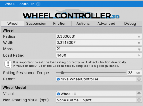
Radius- radius of the wheel in [m].Width- width of the wheel in [m].Mass- mass of the wheel in [m]. Only affects the wheel inertia. Does not affect the vehicleRigidbodymass.Load Rating- maximum load the tire is rated for, in [N]. A good rule of thumb is double the resting Debug ⇒ Suspension ⇒ Spring Force value. Otherwise, can be found through the tire load rating on the sidewall (check the Load Index here, theLoad Ratingwould be the value in kg multiplied by ~10).Rolling Resistance Torque- torque in [Nm] that will constantly be applied as a brake torque to the wheel, and represents the rolling resistance of the tire due to the deformation and other factors. Higher value will result in vehicle stopping sooner when free-rolling.Parent- this is aRigidbodythat the forces will be applied to.Visual- aGameObjectcontaining the wheel mesh. A visual representation of the wheel. It is required that the mesh/model has a correctly centered pivot and has the Unity rotation (Z-forward, Y-up, X-right).Non-Rotating Visual- aGameObjectthat will always be positioned to the same relative point in relation to the wheel, but does not rotate with the wheel. This could be brake calipers, fenders, rigging targets, etc.
Suspension
Suspension settings are fully based on physics, so the general car suspension principles also apply here.
For best results, it is recommended to have the spring length higher than the Project Settings > Time > Fixed Delta Time setting. Lower values, or even 0, are supported but might result in bottoming out of the suspension which will result in a harsh and jumpy ride over bumps. The state of the suspension can be seen under the Debug tab during runtime (bottomed out / normal / fully extended).
Spring
Max Force- the maximum force the spring can exert. This force will be used when the spring is fully compressed (spring length equals zero).- The value of
Max Forceshould be adjusted so that the suspension rests at 30% compression (spring length is 30% of the max spring length, this can be checked through the Debug tab during runtime). - Damper bump and rebound values should be used after the spring is adjusted to make the suspension stiffer and less 'bobby', not the spring
Max Force.
Max Length- maximum suspension length. Suspension extends in the -Y direction of theWheelControllerTransformand is represented by a capital letter “I” white gizmo.- To adjust the ride height do not change the spring length (except in cases where longer suspension travel is needed), instead, adjust the Y position of the
WheelControllerTransforminstead.
Force Curve- default is a straight line from [0, 0] to [1, 1] which means that at 50% of the spring compression, the force will also be half ofMax Force. This can be adjusted to have a custom relationship between spring length and spring force, e.g. a progressive spring.
Damper
Bump Rate- force applied at 1 m/s suspension speed when the suspension is getting compressed (bump). A higher value will make the suspension stiffer when climbing an obstacle or going over a bump.- A too-high value will result in vehicle jitter.
- 5% to 20% of the spring
Max Forceis a good starting point.
Rebound Rate- force applied at 1 m/s suspension speed when the suspension is getting extended (rebound). A higher value will make the suspension take longer to relax after getting compressed.- Same as with the
Max Bump Force, a too-high value will result in vehicle jitter. - Usually is the same value as the
Max Bump Force, or within the +/-50% from it.
- Slow / Fast / Division Velocity - these allow for different damper behaviour at low and high bump or compression speeds. Slow determines the rate coefficient when the damper is moving at a speed below the division velocity, while fast determines the rate above the division velocity. An example of slow damper speed is cornering where the vehicle slowly leans into the corner, while an example of high damper speed is going over a bump or a curb.
General
Suspension Extension Speed Coeff- the speed at which the suspension will be extended once it is in the air. Unitless as it is just a coefficient. A higher value will result in suspension extending faster, but too high a value will look unrealistic. Too low a value will result in suspension that is slow to extend.Force App. Point Distance- distance as a percentage ofSpring Lengthfrom the hit point in the direction of the suspension travel at which the friction forces will be applied. The suspension forces are always applied at theWheelControllerTransformposition. This setting is not physically accurate but it allows for roll elimination without having to utilize an anti-roll bar, since the forces can be applied closer to the center of mass, inducing less roll.Anti Squat- motor and brake torque applied to the wheel will make the vehicle want to rotate around the wheel with the torque opposite to the applied brake and motor torque (since the vehicle acts as a leverage for these forces). This setting either does nothing (-1 = full counter-torque is applied to the vehicle body), applies no torque to the vehicle (0 = no counter torque) or applies an opposite torque (1 = full opposite torque). This means that with acceleration and the setting set to -1 the rear of the vehicle will squat, while with a value of 1, it will raise. The exact behavior also depends on where the center of mass is.Camber- fixed camber value. A negative value will result in the top of the wheel being rotated towards the vehicle, and vice-versa. To use variable camber that changes based on the suspension travel,CamberControllerscript can be used.
Friction
Friction Preset
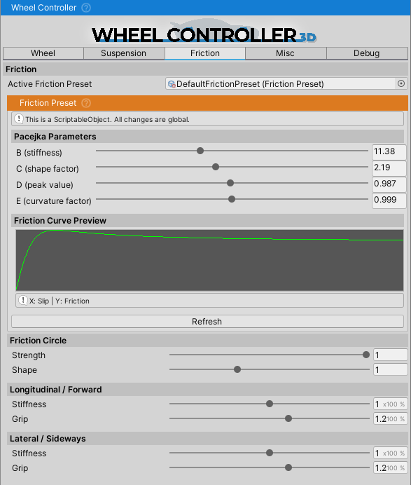
FrictionPreset is a ScriptableObject containing data about the friction properties of a tire.
WheelController's friction is slip-based. Tire always has some slip but it is very small under normal conditions – always near the left side of the curve below.
Image above shows friction curve with slip on the X axis and friction on the Y axis. Part of the curve on the left side marked as “has traction” is where tires normally operate, and part on the right side is where the tire lost traction. Depending on the shape of the curve vehicle will act differently upon losing traction. Here are parameters of the curve and how they affect handling:
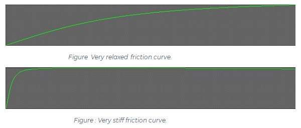
B (stiffness)– With higher value curve will be faster to reach peak value meaning it will be steeper. This means that wheel will require less slip to lose traction and such vehicle will be more unstable – i.e. spin out more easily. With lower values of stiffness vehicle will be more stable and harder to spin but with very low value it will start to act as if on ice.
C (shape)– While stiffness determines where the peak will be, shape determines how strong the knee in the curve will be. High shape value will make it pointy while low value will make it flatter.D (peak)– The higher it is the more traction wheel will have. It does exactly the same thing as Slip Coefficient field does. To simplify, resultant friction is equal to peak value times slip coefficient times some other values - this means that if peak is set to 0.5 and slip coefficient to 2 result will be exactly the same as if both were set to 1 since 0.5*2=1*1.E (falloff)- Determines how fast curve will fall off after the peak. It depends on other parameters but in general lower value will mean that curve ends closer to 0, and value of 1 will mean that it is almost horizontal after the peak. If set to low value vehicle will start to slide once traction is lost and if set to high value there will be almost no difference between “has traction” and “lost traction” parts of the curve.
Friction Circle
- Friction Circle is a circle (or often a sphere) that determines the amount of friction available given the forward and sideways slip. E.g. if there is wheel spin the sideways friction will be greatly reduced. More about the general friction circle concept here (Wikipedia).
- Strength determines how much of an effect the friction circle has. 0 = no effect, 0.5 = only up to half of the forces are affected by it, and 1 = full effect. Having the value at 0 will result in a vehicle that can steer even when the wheels are locked, or when there is wheel spin, but it will prevent the vehicle from doing doughnuts since they depend on the friction circle behavior.
- Shape determines how much of the forward slip can exist before it starts affecting the sideways slip/friction.
Friction Coefficients
Stiffnessis a multiplier for the slip value. Same as theBparameter of the Friction Preset > Friction Curve but is applied on a per-vehicle basis, instead of globally. Lower values will result in vehicle that is less prone to oversteer or losing grip, but will feel floaty. Setting the value too high for the given physics update rate can result in jitter.Gripis a multiplier for the the force value. Same as theDparameter of the Friction Preset > Friction Curve but is applied on a per-vehicle basis, instead of globally. Lower values will result in less grip and, as a result, more floaty behavior. Setting the value too high for the given physics update rate can result in jitter.
Misc
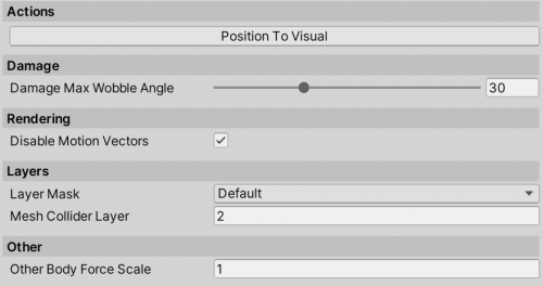
Actions
- Position To Visual positions the
WheelControllerTransformexactly above theVisualTransformposition, with the estimated suspension travel.
Mutliplayer
Visual Only Updatemakes the wheel follow the ground, but not update any physics. This is useful for cases where the vehicle needs to be moved around with the wheels still rotating, e.g. dumbly following a path or being a client vehicle that is not updating the physics.
Rendering
Disable Motion Vectorsmakes the motion blur not apply to the wheels, which avoids glitching that would otherwise happen with Post Processing package.
Layers
Layer Maskadjusts the layers which will be detected by the wheel.Mesh Collider Layer- layer that will be assigned to a MeshCollider that is used for handling edge cases (such as dropping from height, side impacts, no-suspension situations). Check the Considerations section for an explanation of why WC3D uses a MeshCollider.
Other
Other Body Force Scalescales the force applied to the hit Rigidbody. This can be useful in cases of interaction with lighter-weight Rigidbodies, as only a fraction of the suspension and friction forces is applied to the hit Rigidbody, avoiding the physics solver from glitching out. Applying 5000N of force to a 5kg Rigidbody will result in that Rigidbody most likely flying into the air, so using a <1 force scale can be helpful in avoiding this while still keeping the interaction between the two. Can also be set to 0 to not apply any forces to other Rigidbodies.
Debug
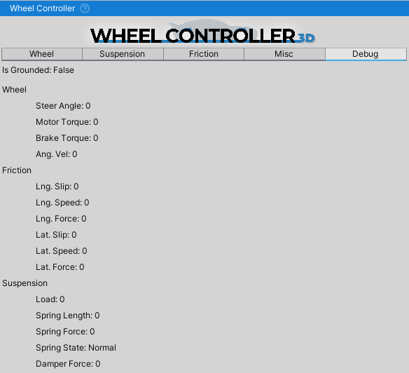
An overview of the WheelController values. It can be helpful in setting up the suspension travel or checking if the suspension bottomed out when going over a bump or landing a jump.
As always, the debug values can also be seen through right clicking the Inspector tab and switching the inspector into the Debug mode.
